
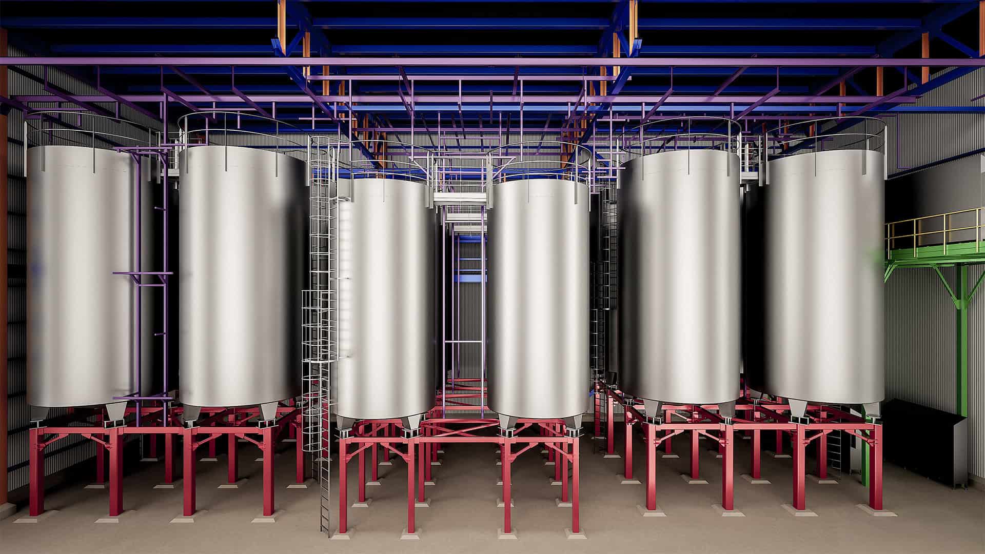
When MEP teams need to coordinate systems or designers need to verify existing conditions before planning renovations, assumptions lead to problems. Manual measurements miss details. Site surveys take time. By the time coordination begins, misalignments surface in the field.
Scan-to-BIM changes that equation. Laser scanning captures existing conditions with a high level of accuracy. That verified data becomes the foundation for a coordinated three-dimensional model—built from what exists on site, not what plans or memory suggests.
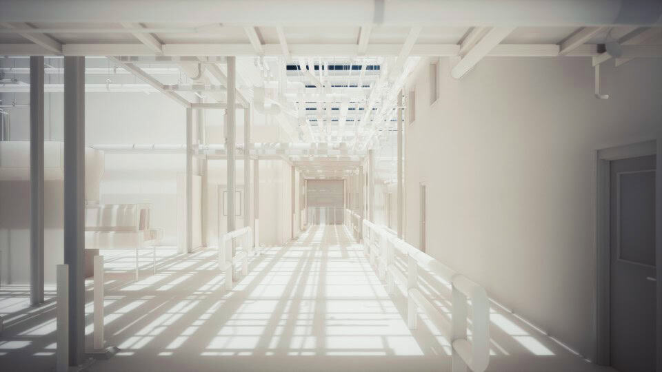
How Our Process Works
Step 1: Planning the Scope
We start by understanding what your model needs to accomplish. Are you planning MEP coordination before construction? Creating MEP spool drawings for mechanical, electrical, or piping system fabrication? Verifying clearances for system tie-ins? Documenting complex geometry before design work begins? This upfront conversation ensures we capture exactly what you need. Focused scanning saves you time and cost by eliminating unnecessary data collection.
Step 2: On-Site Scanning
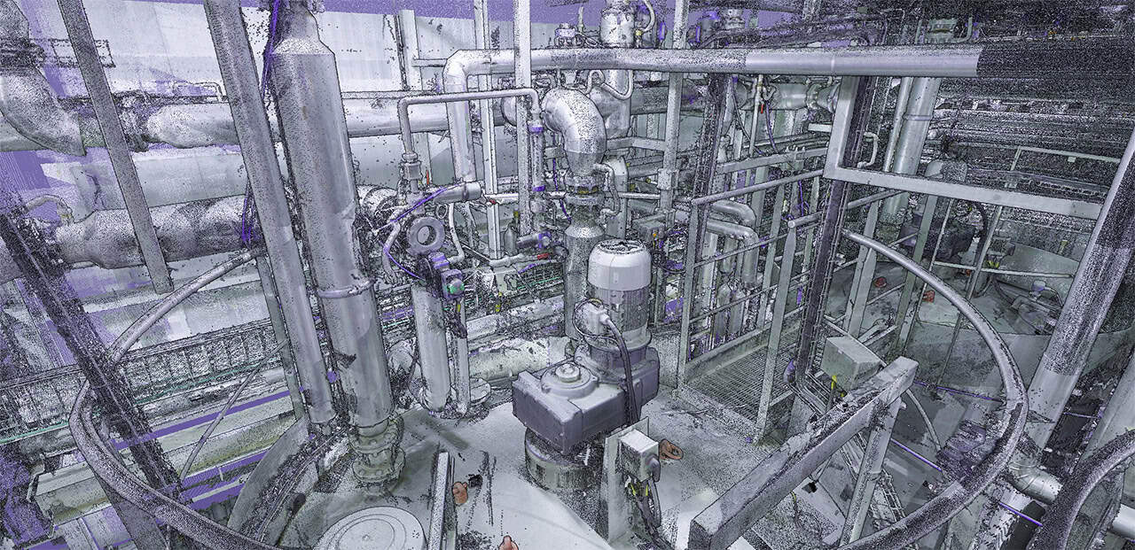
Our scan technician arrives with our Leica RTC360 laser scanner and positions it at optimal locations to capture complete angles and spatial relationships of your space. Experience matters here—our technician knows where to place equipment to ensure comprehensive coverage without redundant data. Once scanning is complete, the point cloud data from multiple positions is aligned and merged into a single, cohesive three-dimensional record of your facility. We export this as an RCP or LGSX file for review and quality control, verifying the data is aligned correctly and there are no mismerges.
Step 3: Model Creation
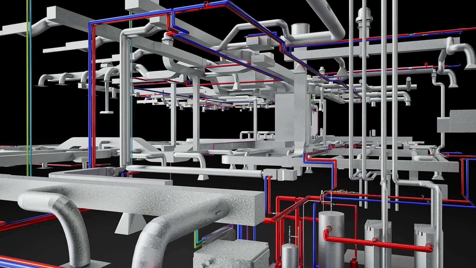
Once the point cloud is approved, we import the data into Revit and align it in orthographic orientation. From there, our BIM specialists trace the point cloud to create a detailed, coordinated three-dimensional model of your building or facility. This model captures building systems, spatial relationships, and accurate dimensions—exactly as they exist on site.
Step 4: Ready for Coordination and MEP Fabrication
Your model is now built on actual site conditions, not estimates. That’s what makes the difference. MEP contractors can coordinate systems with accuracy and speed. Our team can create spool drawings for mechanical, electrical, and piping systems from the verified spatial data. Design teams can plan renovations against known conditions. Clash detection becomes reliable because the model reflects reality.
Why Accuracy and Speed Matter
Traditional existing conditions documentation relies on manual measurements and site surveys. It takes time, requires multiple visits, and inherently introduces gaps in data. Laser scanning, on the other hand, captures comprehensive and accurate information much faster.
The real value isn’t just speed—it’s accuracy that prevents field conflicts. When your coordinated model is built from verified site data, misalignments caused by unknown existing conditions are far less likely. MEP coordination moves faster because teams work from a model they can trust. Our team can prepare spool drawings for piping, mechanical, and electrical systems without field verification, and installation crews receive construction-ready documentation from the start.
What You Get
- High-accuracy point cloud data from your site
- Quality-controlled laser scan aligned for precision
- A coordinated Revit model built from actual site conditions
- Existing conditions documentation as well as coordination and clash detection
- Spool drawings for mechanical, electrical, and piping system fabrication
- Construction-ready documentation your installation crews can rely on
- Confidence that our model reflects your site conditions accurately
Real-World Examples
We’ve completed scan-to-BIM projects across Central Illinois:
- Elevator Shaft Laser Scanning at OSF — Elevator shafts are among the most difficult spaces to document accurately due to tight clearances and complex vertical geometry. We captured this challenging geometry and delivered a coordinated Revit model that guided renovation planning and MEP coordination.
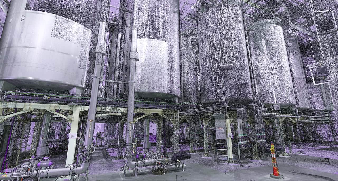
- Tank Farm Laser Scanning and Existing Conditions Modeling — For industrial facilities with complex piping and tank configurations, we documented existing conditions to support design work and MEP system coordination. The client received verified spatial data that enabled confident planning and MEP spool drawing creation without multiple site visits.
- PIPCO Mechanical Room Laser Scanning — Mechanical rooms are dense, intricate spaces where planning new system additions requires accurate knowledge of what’s already there. We delivered a coordinated Revit model showing all existing systems in their actual positions, enabling clash detection, confident design planning, and MEP spool drawing creation for construction.
Ready for Less Stress On Your Next Project?
Verified existing conditions documentation reduces the uncertainty and rework that derail timelines. Instead of managing conflicting measurements or discovering misalignments during coordination, your team works from data everyone trusts. That’s the difference between a stressful coordination process and a confident one.
Explore our 3D laser scanning services and discover how CAD and Revit modeling supports your workflow.