
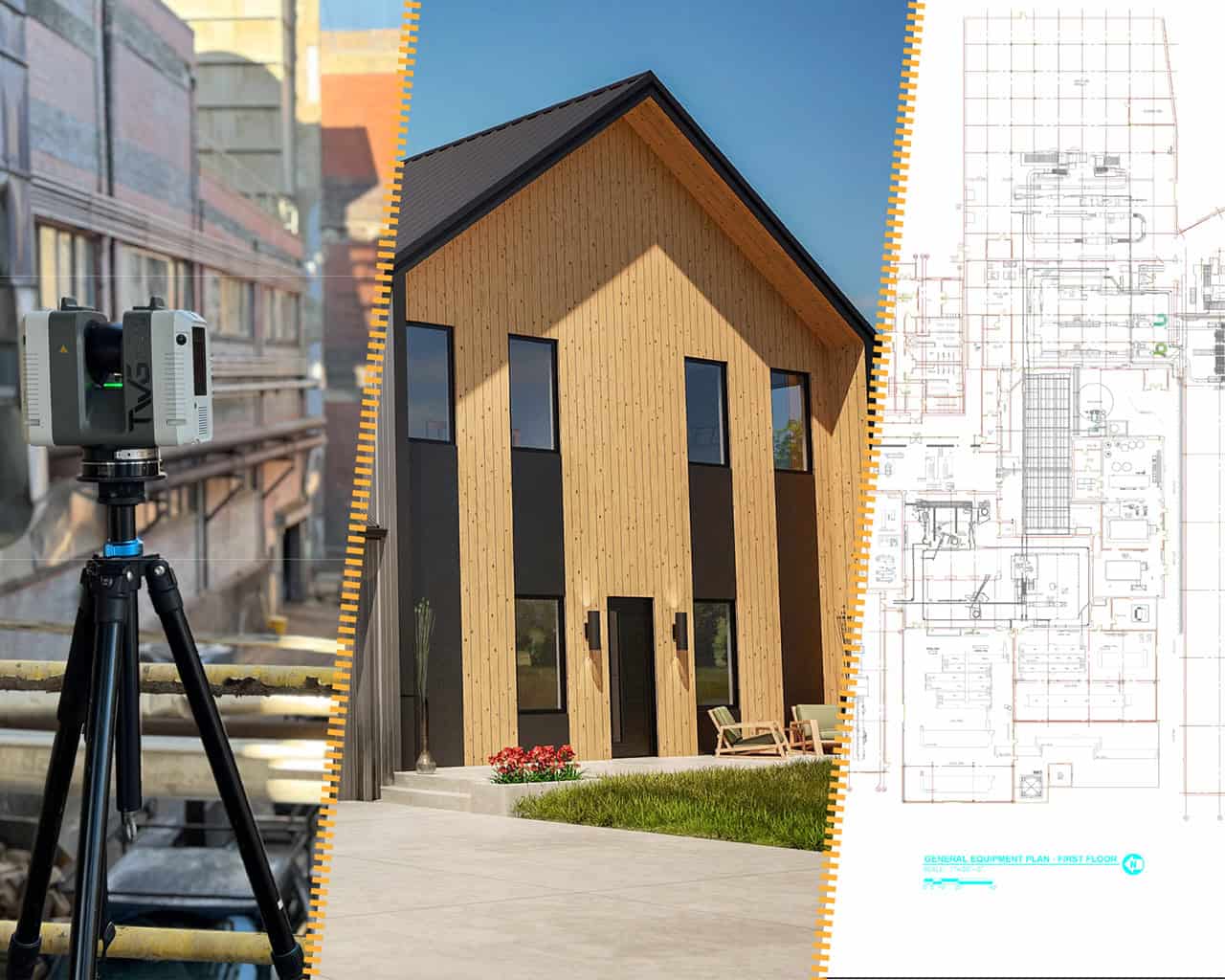
If you’ve received a proposal that includes 3D laser scanning, you may have wondered what actually happens between the scanner arriving on site and your team opening a finished Revit model or CAD drawing set. The process involves more steps than most clients expect. Moreover, it requires more careful judgment than the technology alone suggests.
This post walks through TWG’s full workflow from start to finish. Every detail reflects how the process genuinely works on a real project — not a simplified version of it.
Step 1 — Preparing the Site Before Scanning Begins
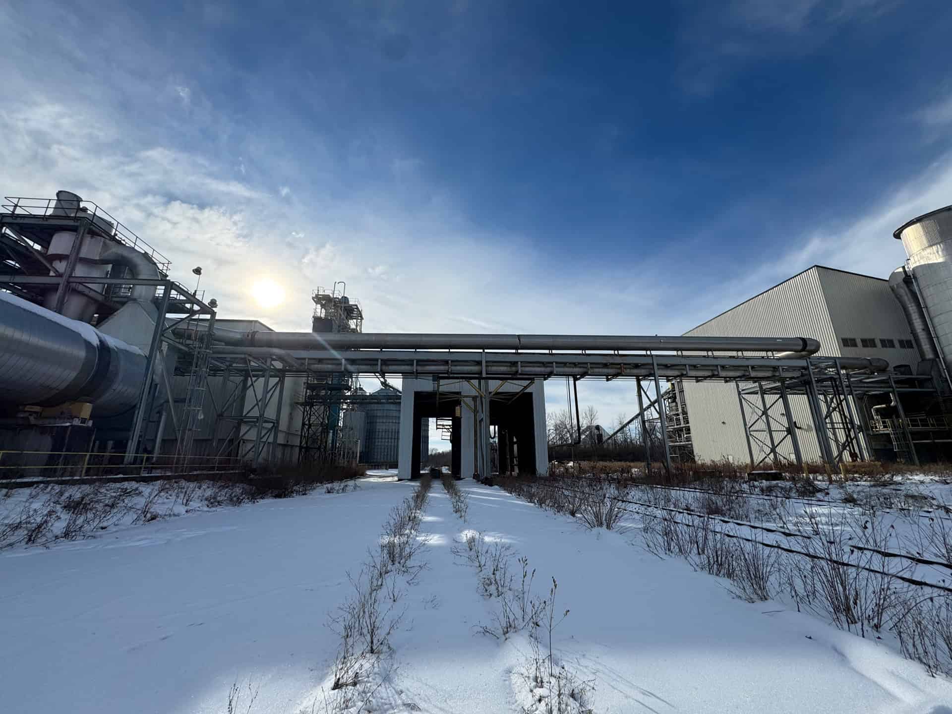
Good scanning starts before the scanner is switched on. TWG’s first priority on any site visit is understanding the space. The team needs to know what requires capture, how to cover it efficiently, and what might get in the way.
When floor plans are available in advance, TWG reviews them before arriving. The team plans a scanning route, identifies problem areas, and thinks through access points that might need coordination. For outdoor areas and unfamiliar sites, satellite imagery helps establish context before the team sets the first scanner position.
When a project begins without prior documentation — which happens regularly on older buildings — TWG walks the entire space first. This walkthrough is deliberate. The team identifies the most efficient scanning route and clears debris or obstructions so the scanner can capture features cleanly. In addition, the team determines where additional lighting or equipment like ladders is needed and locates any locked areas that require access.
Rather than interrupting operations repeatedly throughout the day, TWG identifies all access needs upfront. This allows a single coordinated trip to grant access to restricted areas. On larger or more complex sites where a complete walkthrough isn’t practical before scanning begins, TWG continues this preparation progressively — assessing and preparing each new area between scans as the work moves through the building.
Step 2 — Scanning With the Leica RTC360
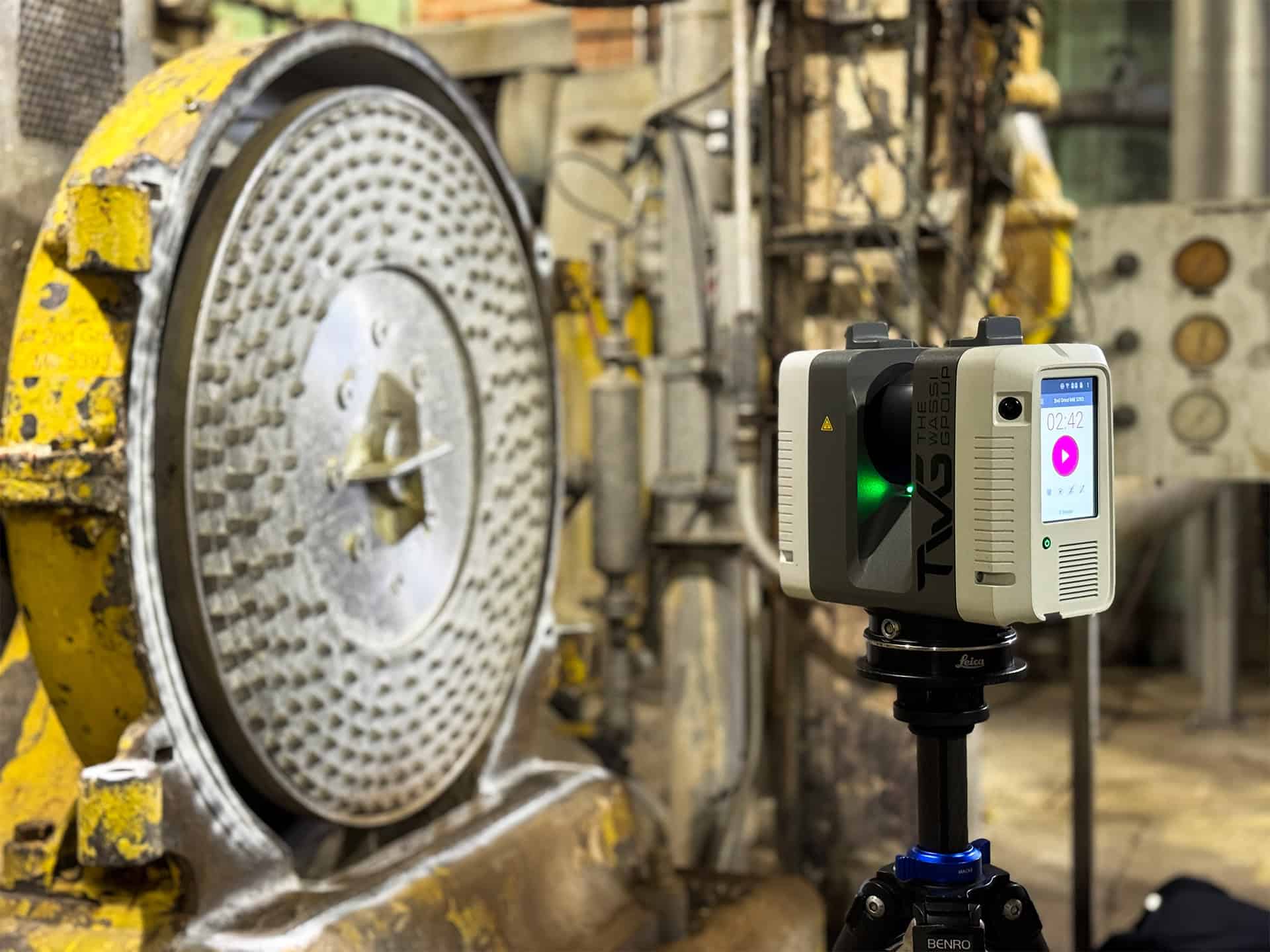
TWG’s primary scanner is the Leica RTC360. It captures millions of accurate measurements per second and serves as the foundation for every scan-based project TWG delivers. For certain projects, TWG also uses the Leica BLK360 — a more compact scanner that covers the same fundamentals in a smaller, more portable package.
The number of scan positions a project requires varies significantly. Scope, building complexity, and capture requirements all drive that number. Most TWG projects fall somewhere between 20 and 500 individual scan positions. A small residential addition requires far fewer. A large multi-building industrial facility requires far more. There’s no standard number because every project is different.
Another important step also takes place during scanning. As TWG captures scan positions, the team uses the Leica Field360 app on site to begin linking positions in real time. This allows the team to identify and address coverage gaps immediately. Rather than discovering problems during post-processing back at the office, TWG catches them while still on site. The team also names individual scan positions during this process, which streamlines registration significantly.
Step 3 — Registering the Scans With Cyclone REGISTER 360
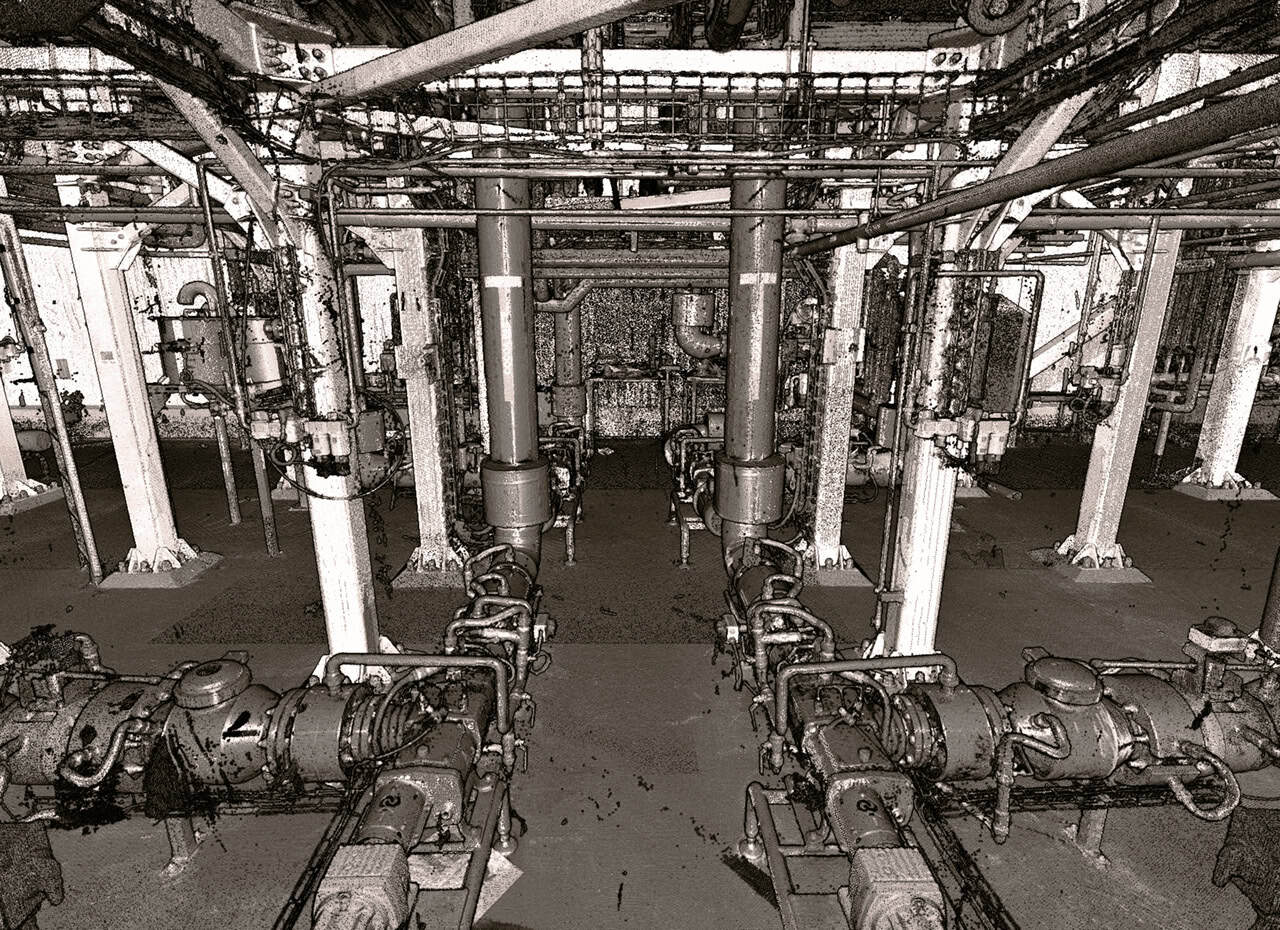
Once scanning is complete, TWG aligns and merges all individual scan positions into a single cohesive three-dimensional record of the space. This process is called registration. TWG uses Cyclone REGISTER 360 from Leica exclusively for this step.
Cyclone REGISTER 360 handles both registration and broader post-processing efficiently. It also exports to every file format TWG’s projects require — making it the right tool for delivering clean, accurate scan data in whatever format a project calls for.
How long registration and post-processing takes depends entirely on the project. Site conditions, scanner settings, control networks, and the complexity of required deliverables all affect the timeline. Smaller projects can occasionally take longer due to challenging site conditions. Larger ones, with clear site conditions, sometimes process quicker. Registration typically moves faster than post-processing. In part, this is because TWG already linked scan positions in the field using Field360 during the scanning phase — removing a significant portion of the registration work before post-processing begins.
Step 4 — Quality Control Before Modeling Begins
Before modeling starts in Revit, TWG puts the registered point cloud through a dedicated quality control review. This step is easy to overlook from the outside. However, it’s one of the most important parts of the process.
TWG imports the point cloud into Revit and reviews it carefully using slice sections. These are horizontal and vertical cuts through the data that reveal how accurately the scans captured each area of the building. Reviewing the data in Revit with fresh eyes catches things that automated processing occasionally misses.
TWG also needs to orient the point cloud to a precise orthographic position before modeling begins. The team exports scans from Cyclone in an approximately orthographic orientation — but fine-tuning is always required once the data arrives in Revit. TWG then sets floor levels for the project and aligns the point cloud vertically to those levels. Only after confirming that alignment does modeling begin. For projects that require georeferencing, TWG adjusts this process accordingly.
Step 5 — Building the Revit Model
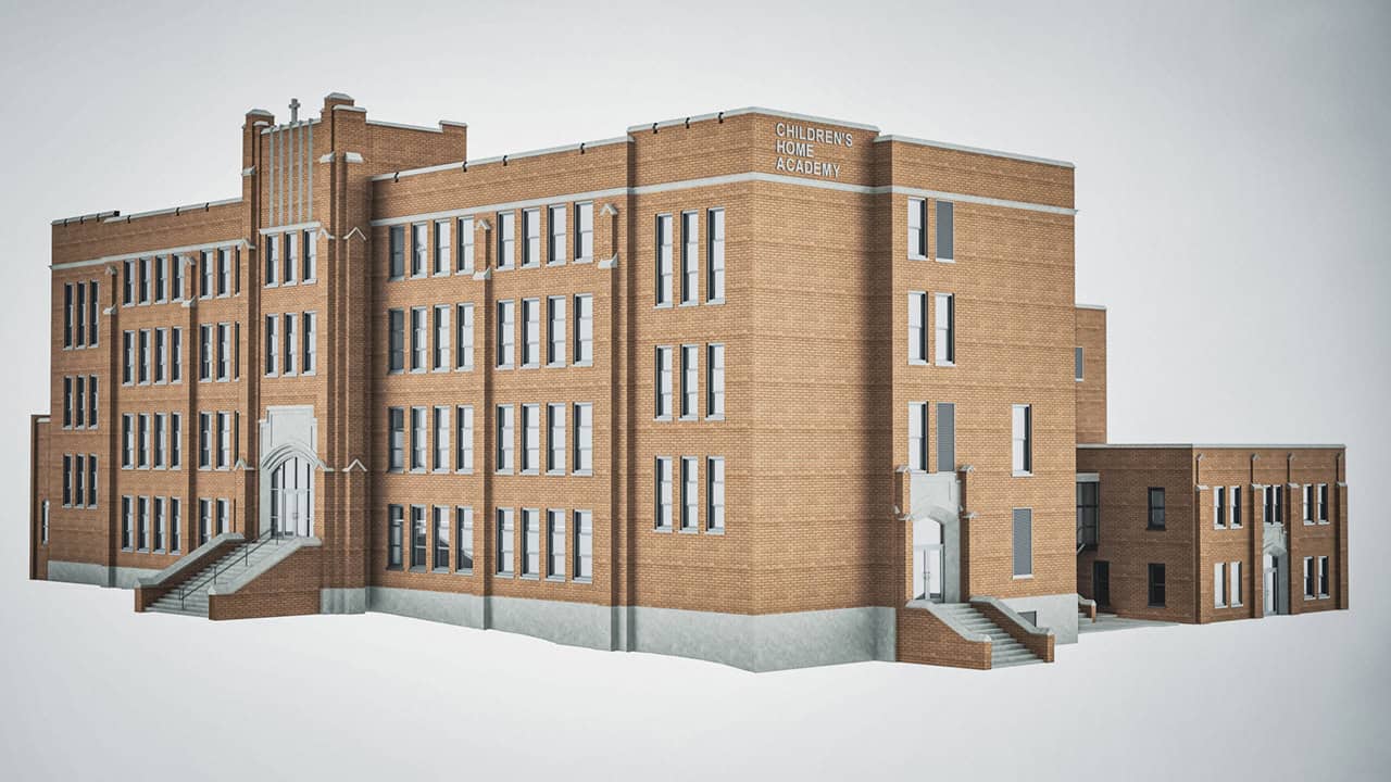
With a properly oriented point cloud in place, TWG’s CAD team begins building the Revit model. The team traces the point cloud to produce a coordinated three-dimensional representation of the existing building or facility.
This is where one of the most distinctive aspects of TWG’s work becomes clear — and it’s something most clients don’t see directly. Building an accurate and usable Revit model from point cloud data requires a constant stream of judgment calls. The raw point cloud captures reality precisely. It records every imperfection, irregularity, and variation in the physical building. The challenge is knowing when to represent those variations faithfully and when to smooth them for usability.
A floor with subtle undulations is a good example. A perfectly literal representation of every variation might be technically accurate. However it would produce a drawing that’s difficult to work from in the field. A contractor pulling a tape measure needs a reference point that makes practical sense — not a document mapping every millimeter of an uneven slab. Similarly, an older wall with minor left-to-right irregularities needs representation that communicates its actual position without making the drawing unnecessarily complex to use on site.
Getting this balance right requires experience and careful judgment. It also requires a clear understanding of how the deliverable will actually be used once it leaves TWG’s hands. The goal is always a model that is both accurate and practical.
Step 6 — Final Deliverables
What a client receives at the end of a TWG project depends on what their team actually needs. Deliverables vary from project to project — and TWG designs that flexibility into the process intentionally.
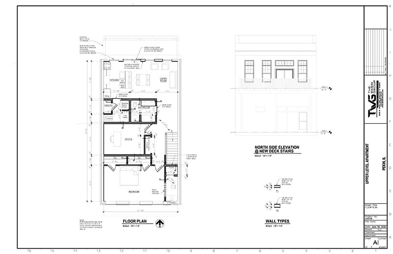
Some clients need only the raw point cloud data. Others need only PDF drawing sets for permit submissions or construction coordination. Others require the complete package — native Revit project files, point cloud data, PDF drawing sets, and any additional documentation the project calls for.
TWG discusses deliverable requirements at the start of every project. This ensures the workflow is set up correctly from the beginning — from how the team captures scans in the field through how they export and format files for delivery. The right conversation at the start of a project prevents surprises at the end.
Why the Process Matters
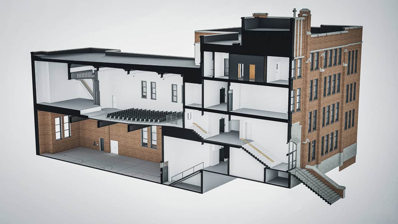
Every step in TWG’s workflow exists for a reason. The on-site walkthrough prevents coverage gaps and access delays. The Field360 connection during scanning speeds up registration and catches issues before the team leaves the site. The quality control review in Revit catches what automated processing misses. The judgment calls during modeling produce drawings that are both accurate and genuinely usable in the field.
None of these steps are obvious from the outside. Together, however, they separate a deliverable your team can actually build from — from raw data that requires extensive rework before it becomes useful. That’s the standard TWG holds itself to on every project regardless of size or scope.
Ready to Get Started?
TWG works with architects, contractors, facility managers, and industrial clients throughout Illinois and beyond. Whether your project calls for 3D laser scanning, CAD drafting and Revit modeling, or construction printing, our goal is always the same — give your team accurate, reliable documentation you can build from.
If your project is in the region, visit our dedicated page for 3D laser scanning in Central Illinois to learn more about how TWG supports local project teams.